To generate plasma, we apply an electrical field to a gas, with the goal of removing electrons from their nuclei. These free-flowing electrons give the plasma key properties, including its electrical conductivity, a magnetic field, and sensitivity to external electromagnetic fields.
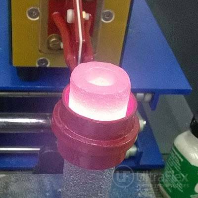
In this application test, the customer provided sample parts to be induction heated. Ultraflex demonstrated the ability of the UPT-SB High Frequency Induction system to heat the stainless steel cup to 2700-28000F within three minutes. This demonstrated the feasibility of the system for Induction Heating Silicon Carbide for plasma research.
Materials
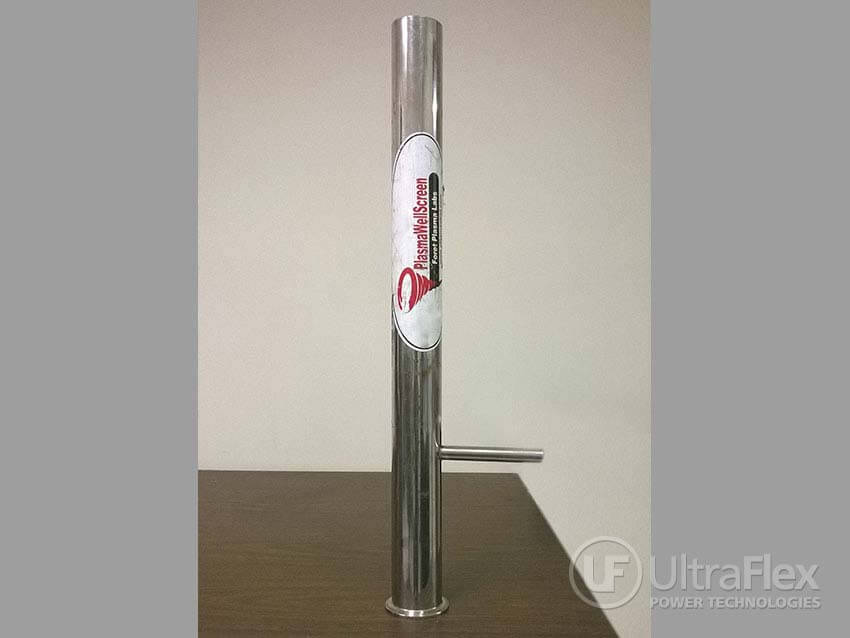
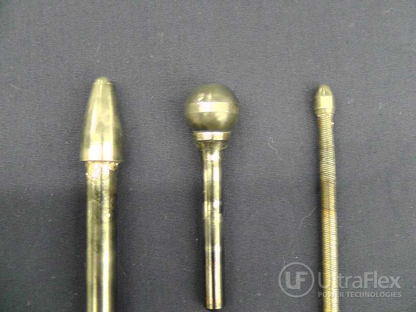
• Silicon Carbide cylinder, with 1.22” OD and 0.5” ID
• Silicon Carbide cylinder, with 1.22” OD and 0.5” ID
Key ParametersTemperature: 2700-28000F
Power: 1 kW
Time: 180 seconds
Frequency: 1 MHz
Power: 1 kW
Time: 180 seconds
Frequency: 1 MHz
Process:
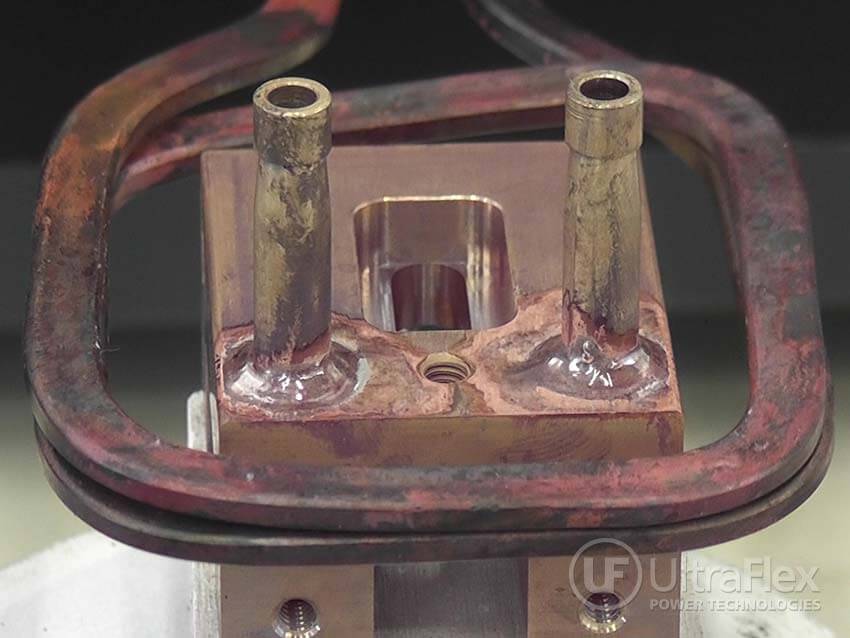
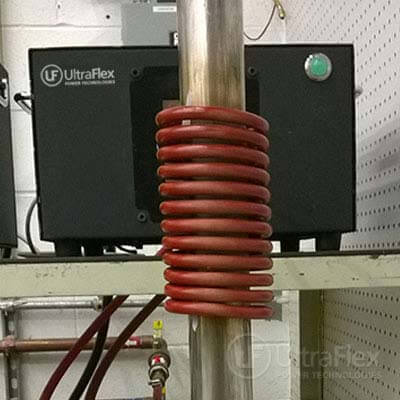
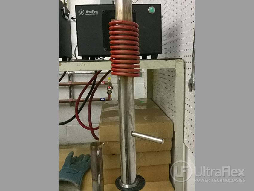
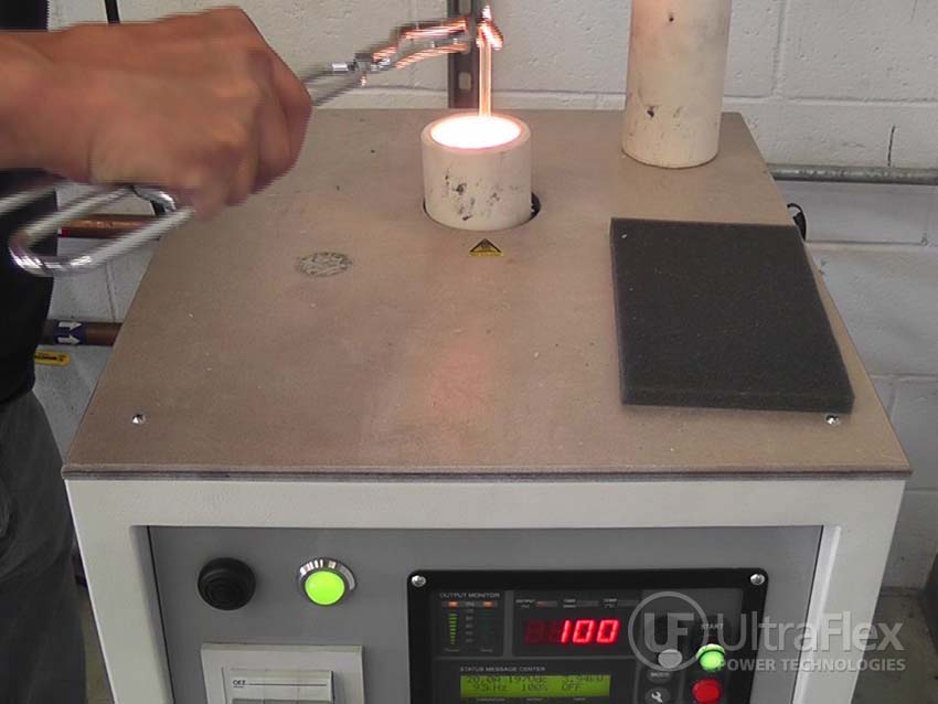
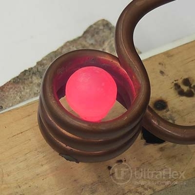
- The silicon carbide cylinder was centered in a single turn coil.
- The UPT-SB3, which operates up to 1 MHz was turned on.
- The part was heated to approximately 2700-2800oF in 180 seconds. This demonstrated the feasibility of this system for Induction Heating Silicon Carbide for plasma research.
Results/Benefits:
- Precise control of the time and temperature
- Power on demand with rapid heat cycles
- Repeatable process, not operator dependent
- Safe heating with no open flames
- Energy efficient heating
Pictures
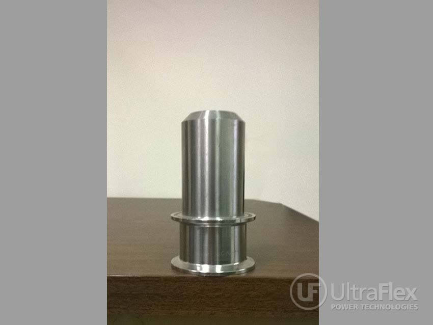
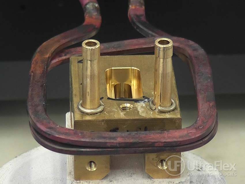
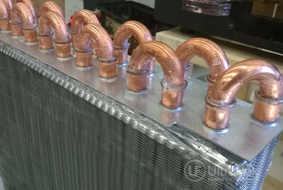
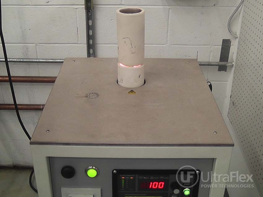
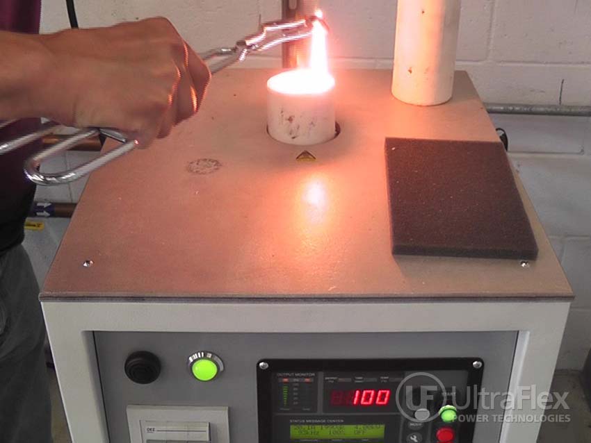
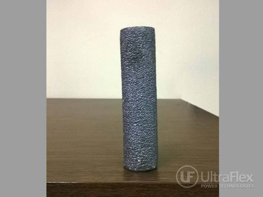 |
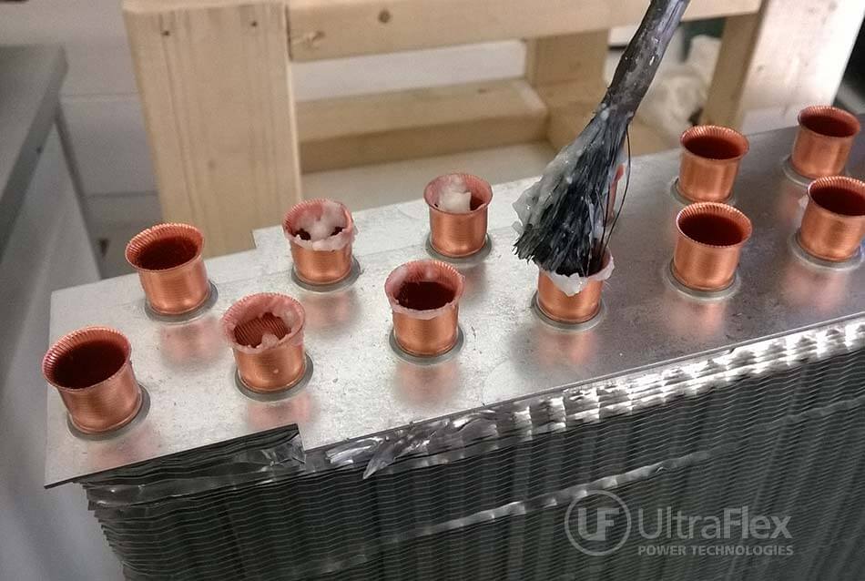
| Silicon Carbide Cylinder |
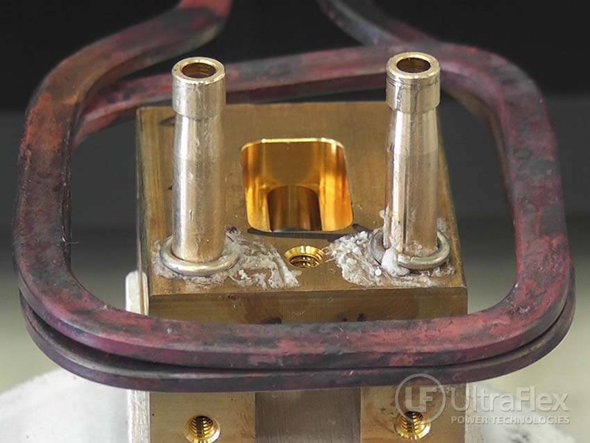
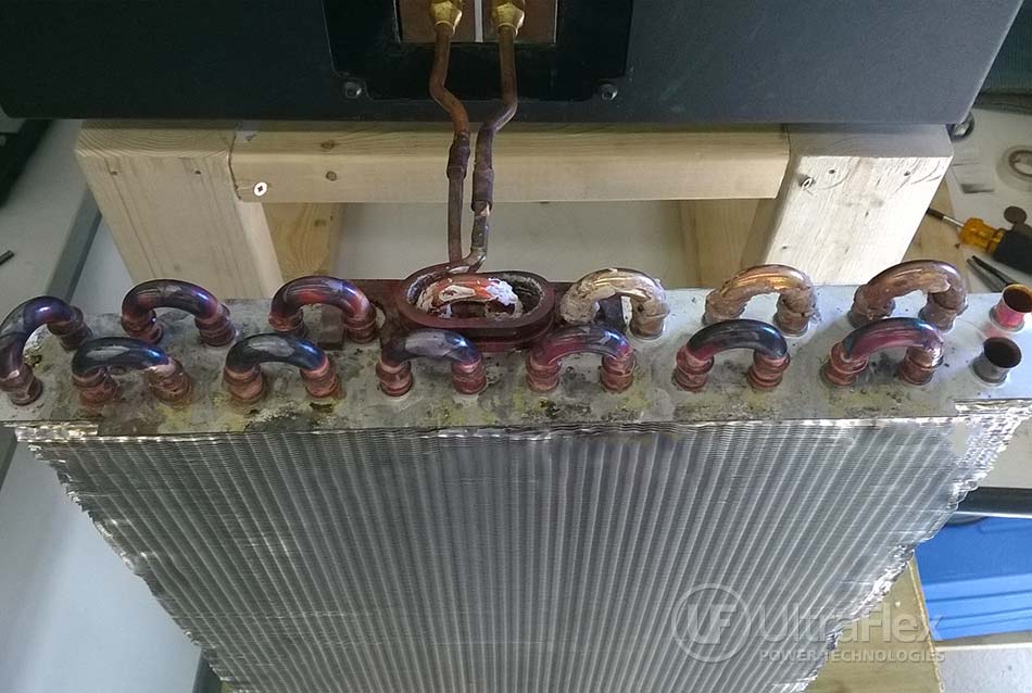
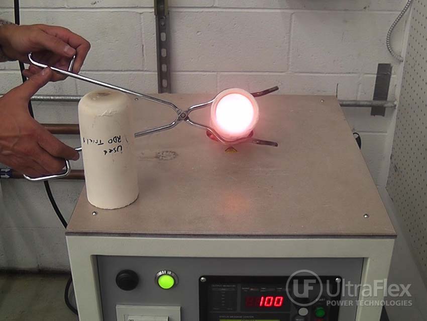
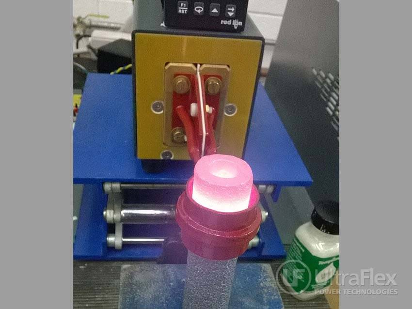 |
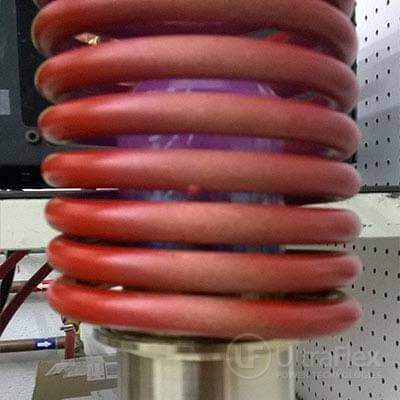
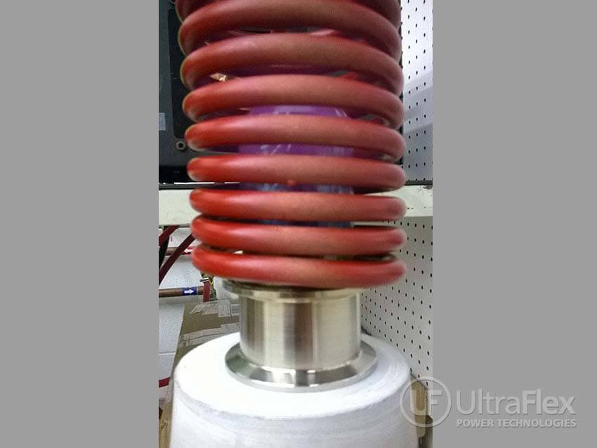
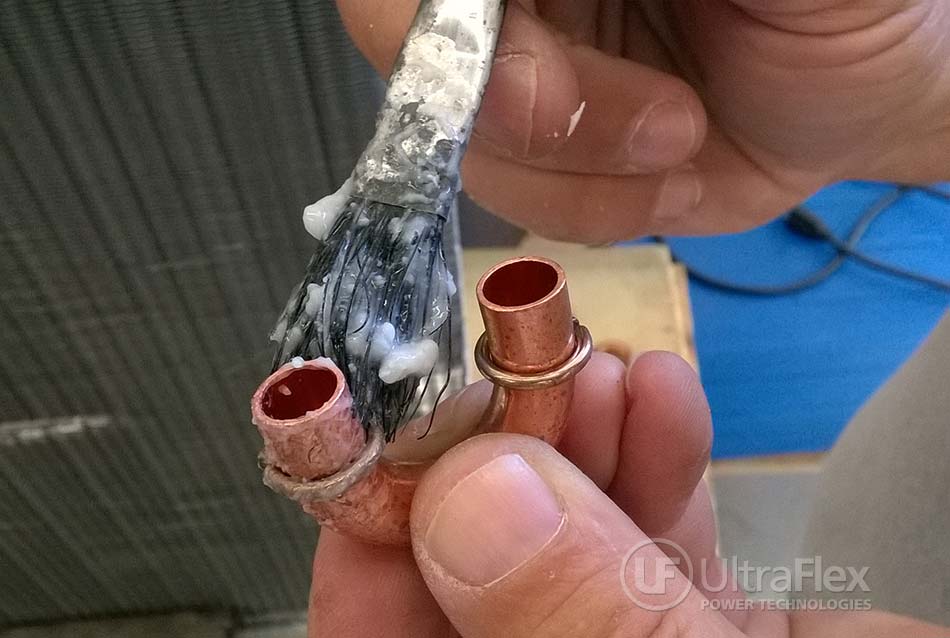
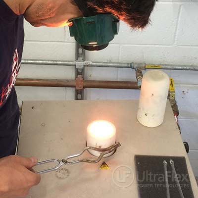
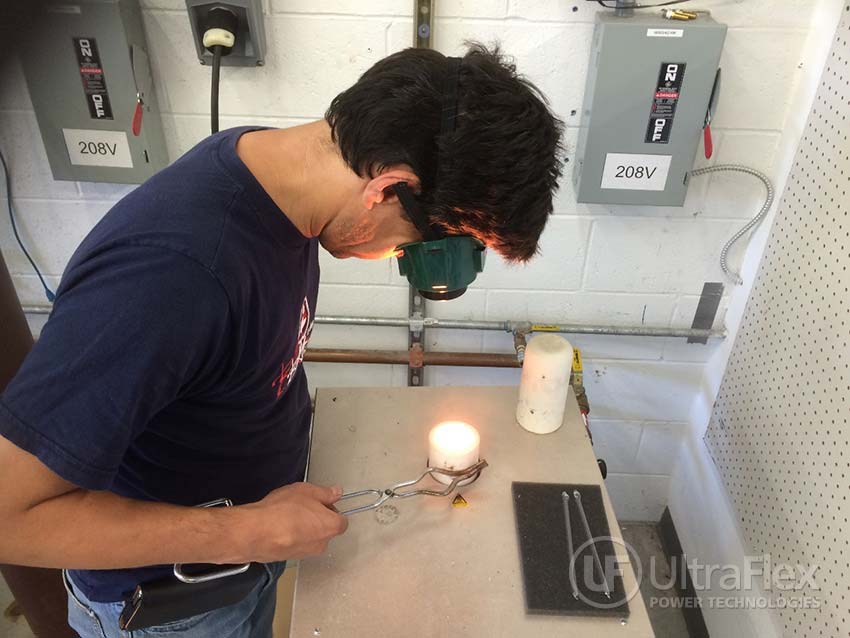
| Slilcon Carbide Cylinder heated to 2700-2800 F with 1 MHz Induction. |
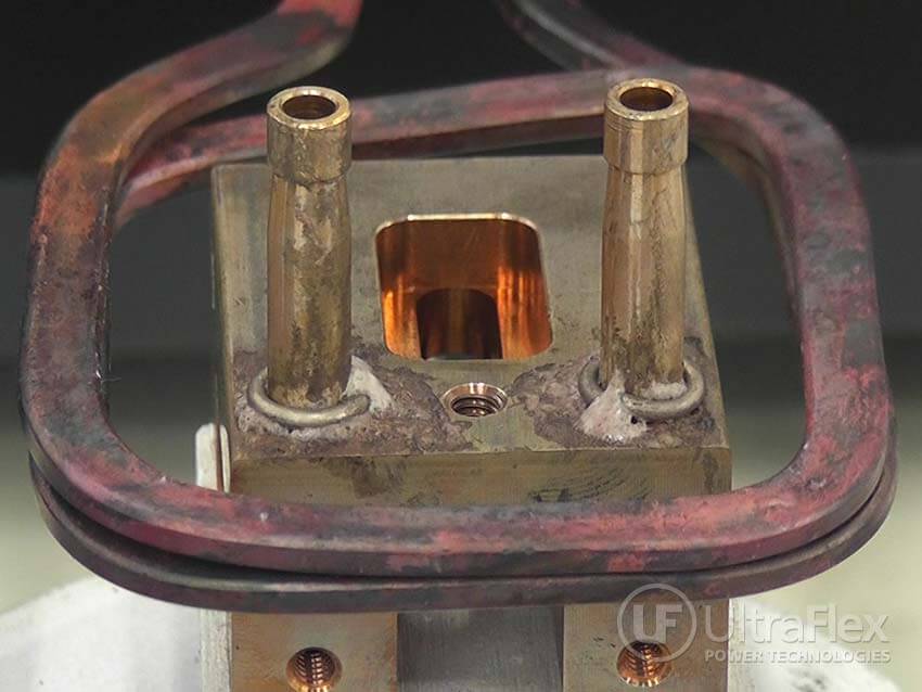
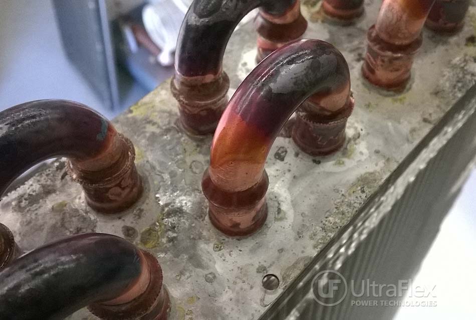
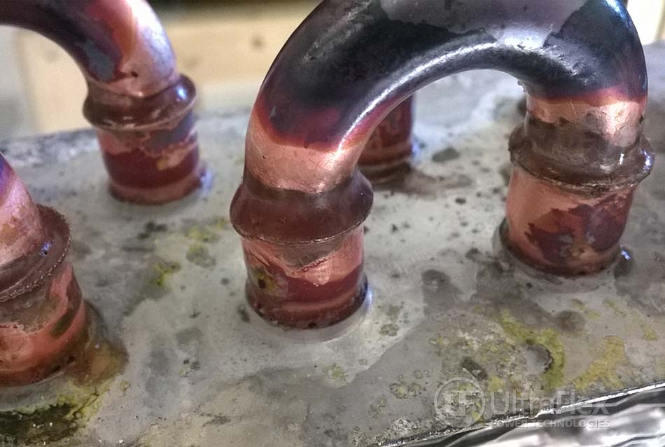
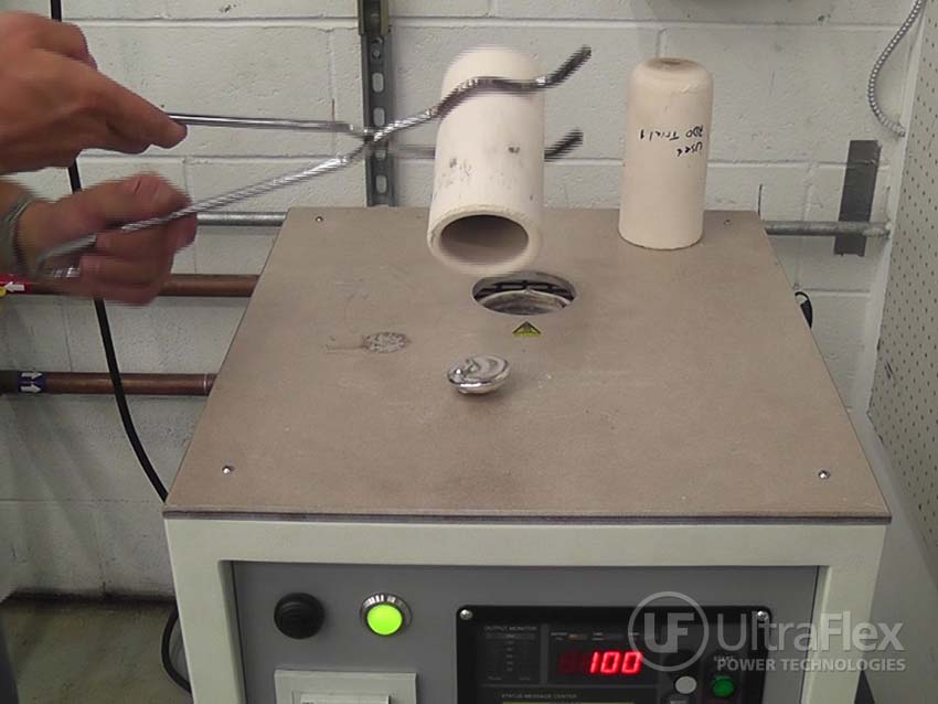
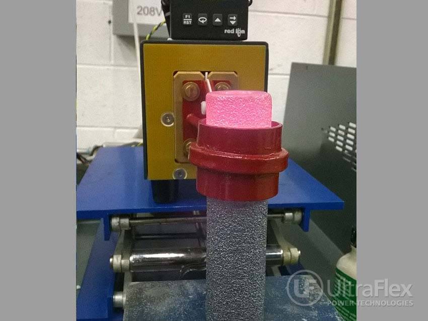 |
| Slilcon Carbide Cylinder heated to 2700-2800 F with 1 MHz Induction. |