The objective of this application test is to determine heating times for soldering copper connectors onto a copper coaxial cable. The customer would like to replace hand soldering with soldering irons, with induction soldering. Hand soldering can be labor intensive, and the resulting solder joint is highly dependent on the skill of the operator. Induction soldering allows finite process control, and provides a consistent result.
Equipment
Materials
• Copper Coaxial Cable
• Plated copper connectors
• Copper bullet-shaped internal connector
• Copper pin-shaped internal connector
• Solder wire
• Carbon steel
• Plated copper connectors
• Copper bullet-shaped internal connector
• Copper pin-shaped internal connector
• Solder wire
• Carbon steel
Key Parameters
Test 1: Soldering Copper Coax Center Conductor to Bullet-Shaped Center Pin
Temperature: ~400F
Power: 1.32 kW
Time: 3 seconds for bullet connector
Frequency: 235 kHz
Key Parameters
Test 2: Soldering Copper Coax center conductor to Needle-Shaped Center Pin
Temperature: ~ 400F
Power: 1.32 kW
Time: 1.5 second for needle connector
Frequency: 235 kHz
Key Parameters
Test 3: Soldering Copper Coax to the End Connector (Bullet-Shaped Center Pin)
Temperature: ~ 400F
Power: 1.8 kW
Time: 30 seconds of heating time, followed by a 10 second cooling cycle
Frequency: 197 kHz
Key Parameters
Test 4: Soldering Copper
Coax to the End
Connector
(Needle-Shaped Center Pin)
Coax to the End
Connector
(Needle-Shaped Center Pin)
Temperature: ~ 400F
Power: 1.86 kW
Time: 30 seconds of
heating time, followed by a
10 second cooling cycle
heating time, followed by a
10 second cooling cycle
Frequency: 199 kHz
Process:
For each type of center pin, the soldering process has two steps. First, soldering the center pin (bullet-shaped or needle-shaped) to the center conductor of the coaxial cable; and second, soldering the coaxial cable with the pin into the end connector
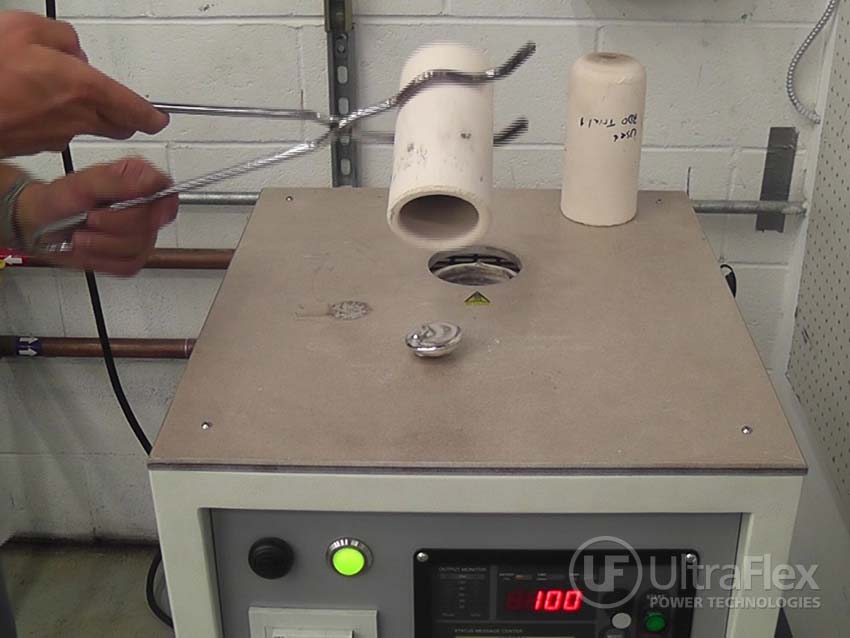
Tests 1 and 2: Soldering copper coax center conductor to the connector center pin
- The internal connector pin (needle and bullet followed the same process) were assembled to the coaxial cable center conductor. A solder slug roughly ½ the length of the pin where the wire is to be soldered, was cut and placed in the receiving end of the center pin. The copper conductor of the coax was positioned to rest on the solder slug in the pin with light pressure downward.
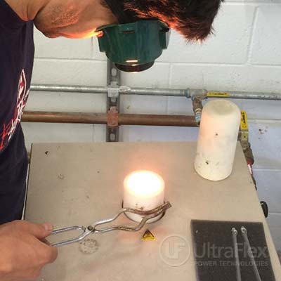
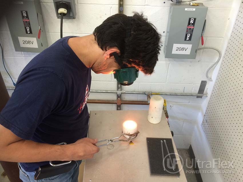
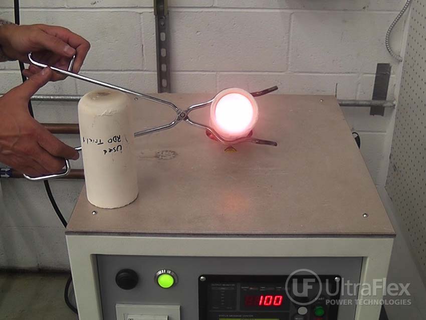
- The assembly was placed into a two-turn induction coil, and power was turned on.
- As the solder melted, the copper conductor of the coax seated into the center pin. The assembly was held still for several more seconds as the solder cooled. Note: it is important to keep the solder joint still until it has cooled. If movement occurs, a “cold” solder joint can result.
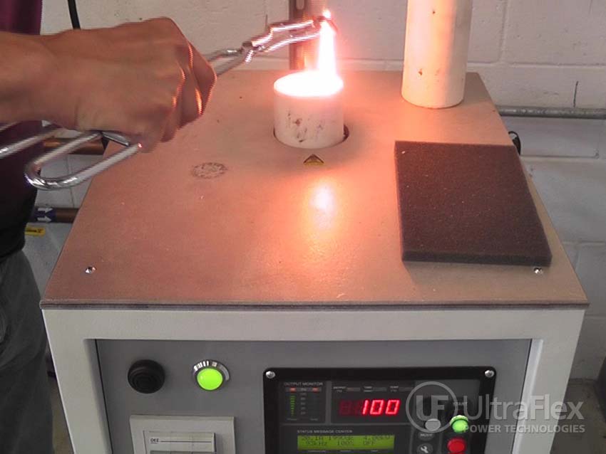
Tests 3 and 4: Soldering copper screw-type end connector to the Center Pin
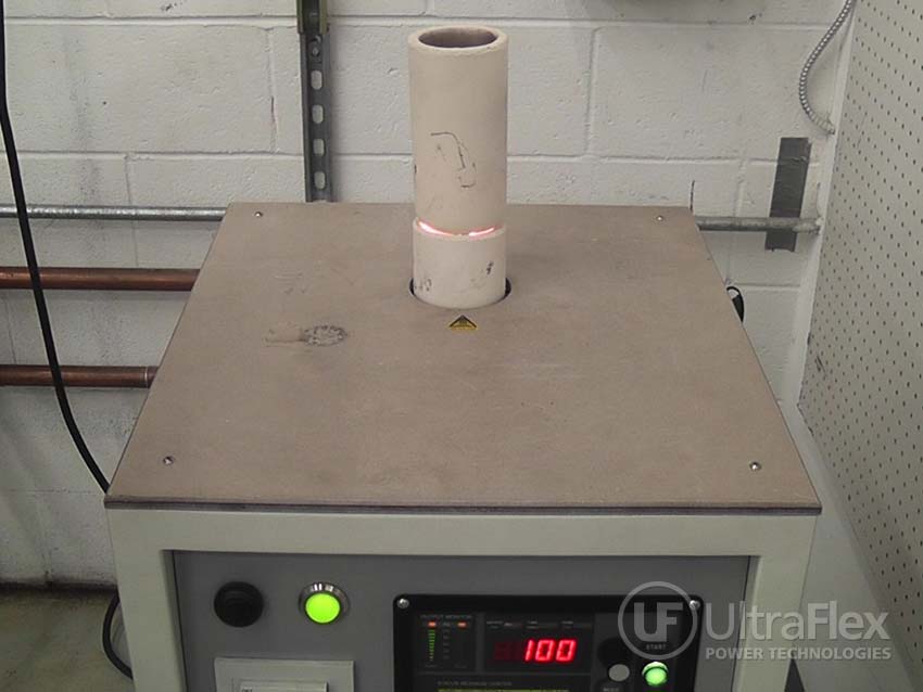
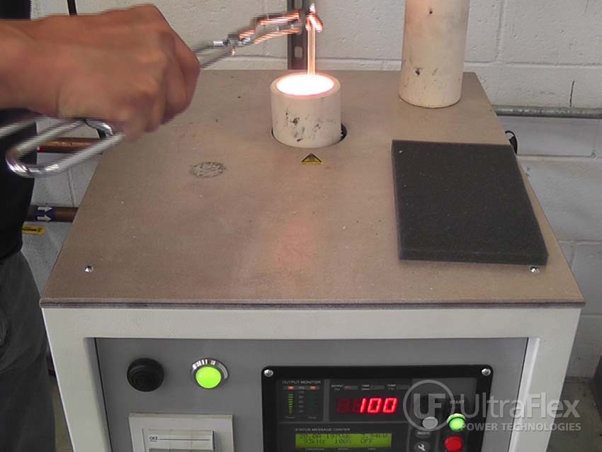
- Solder wire was wound around the corrugated flutes of the coax. The coax with solder was placed into the end connector.
- The assembly was placed into a u-shaped induction coil, and power was turned on.
- Heat time – 30 seconds for either assembly followed by a 10 second hold to let the alloy solidify.
Results/Benefits:
The soldering was successful, and confirmed that induction is an excellent alternative to hand soldering.
- Precise control of the time and temperature
- Power on demand with rapid heat cycles
- Repeatable process, not operator dependent
- Safe heating with no open flames
- Energy efficient heating
Pictures
Videos
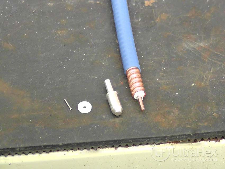 |
| Components for the Bullet End Assembly |
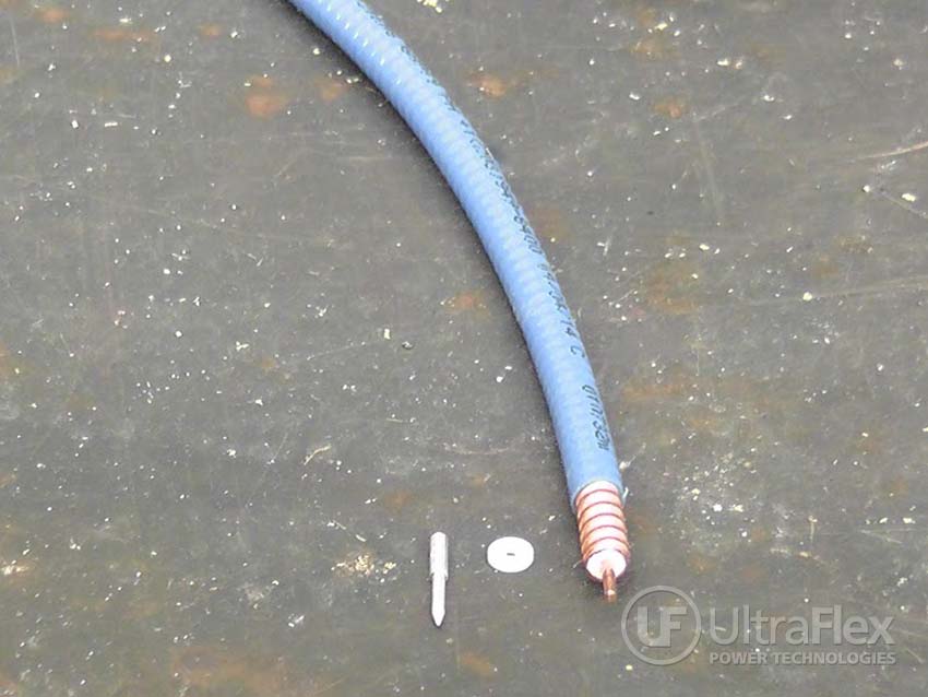 |
| Components for the Needle End Assembly |
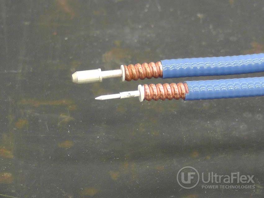 |
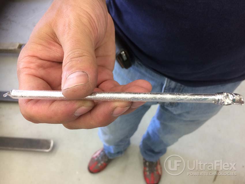
| Completed Solder Joints - Bullet End and Needle End to the Coax Center Conductor |
 |
| Test 3: Solder is would around the corrugated coax. |
 |
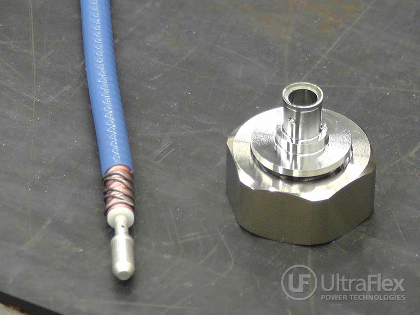
| Test 3: Assembled prior to solder cycle. |
 |
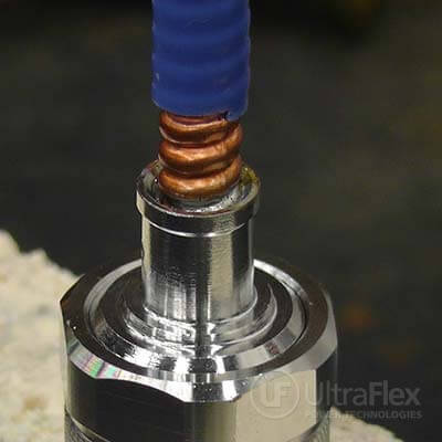
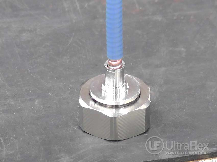
| Finished assembly. |
Videos
Test 1
Test 2
Test 3
Test 4
Ultraflex Power Technologies provides Induction Heating Solutions for your heating challenges.
Contact us today about your heating application!