Thursday, July 30, 2015

Brazing Carbide to Steel

Application Test Objective is Brazing Carbide to Steel, confirming the heating time.  Customer provided samples of carbide tips of various sizes and shapes to be brazed to a steel shanks of various sizes and shapes.  Confirm brazing feasibility and heating times using Ultraheat UPT-S5 5 kW for brazing carbide to steel.

Equipment
Materials
• Magnetic Steel Shanks
• Carbide Tips
• Alloy – EZ Flo 45 paste
Test 1 
Magnetic Steel Shank OD: 0.375”
Cone-Shaped Carbide Tip with taper from 0.5” OD to 0.062” at the peak
Key Parameters
Temperature: approximately 1450F
Power: 1.3 kW
Time: 35 seconds
Frequency: 115 kHz

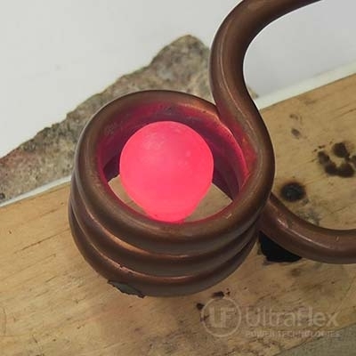
Test 2 (See Video 1)
Magnetic Steel Shank OD: 0.250”
Spherical Carbide Tip with 0.638” diameter, and flat underside of 0.431”
Key Parameters
Temperature: approximately 1450F
Power: 1.5 kW
Time: 21 seconds
Frequency: 116 kHz

Test 3 (See Video 2)
Magnetic Steel Shank OD: 0.180”
Bullet-shaped Tip with major OD 0.264”
Key Parameters
Temperature: approximately 1450F
Power: 0.6 kW
Time: 13 seconds
Frequency: 114 kHz


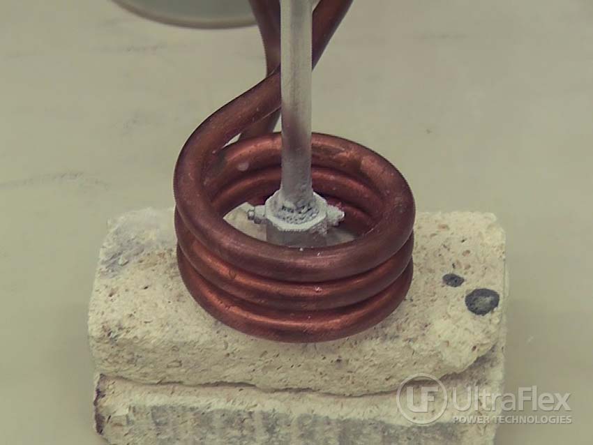
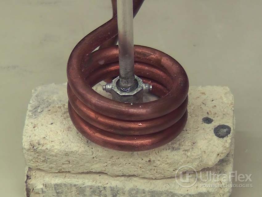
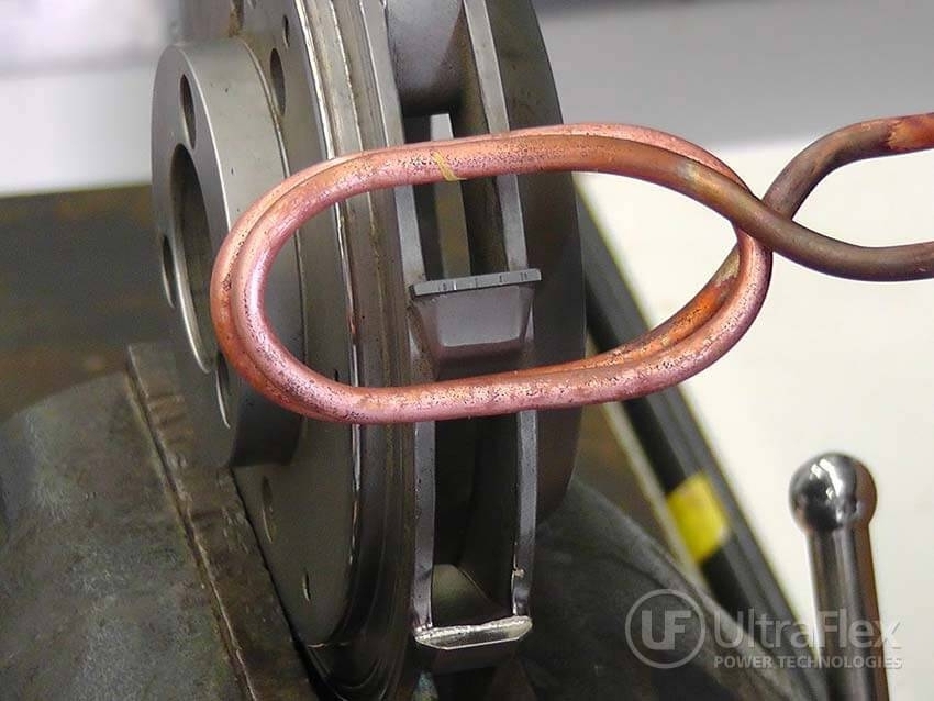
Process for Brazing Carbide to Steel:
  1. The magnetic steel shank and carbide were cleaned.
  2. Paste alloy was added to the interface area between the shank and carbide.
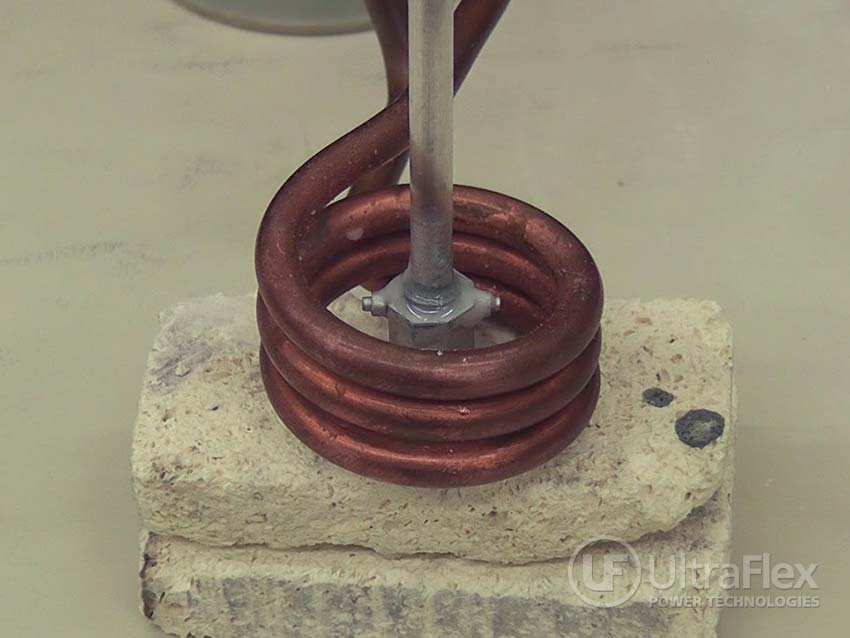
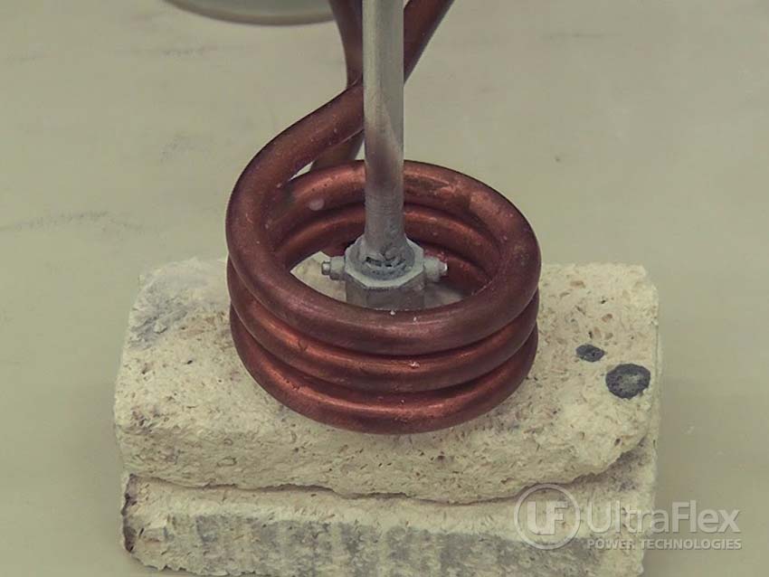
  3. Simple fixtures were used to hold the shaft in place, and hold the carbide in place.
  4. Power was turned on, and the parts were monitored to confirm when the braze was complete.
Results:
All parts were brazed successfully, using the same coil and tap settings on the induction equipment. No equipment changeovers are necessary.
A formal fixture to ensure the parts are aligned during the brazing process is recommended.
Benefits:
  • Precise control of the time and temperature
  • Power on demand with rapid heat cycles
  • Repeatable process, not operator dependent
  • Safe heating with no open flames
  • Energy efficient heating
Pictures
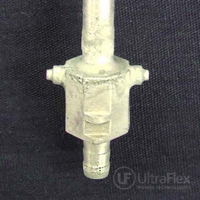
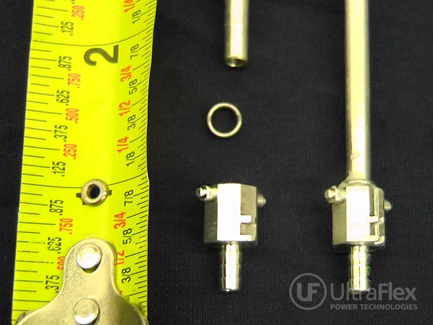
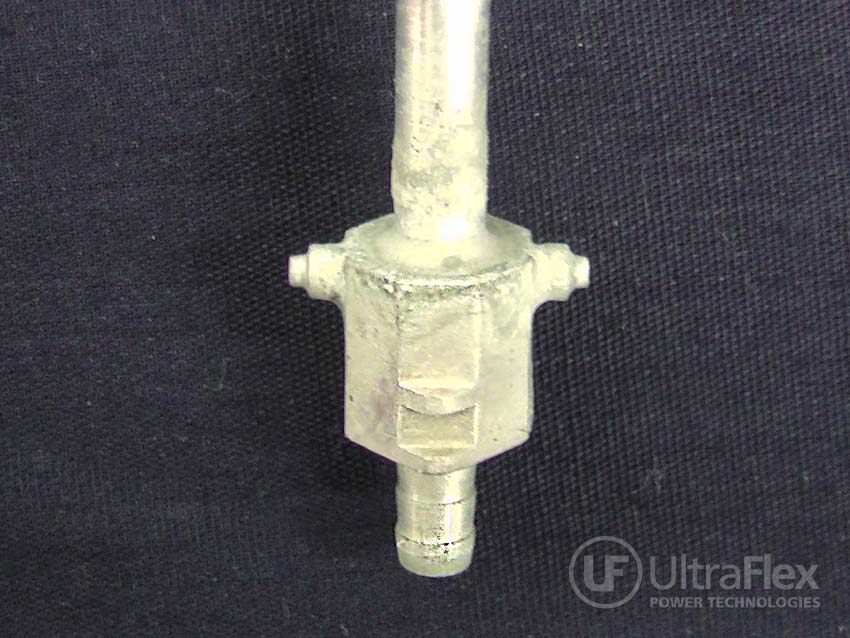
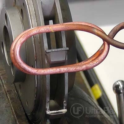
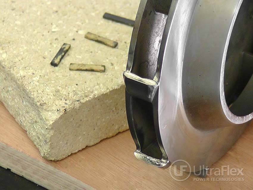
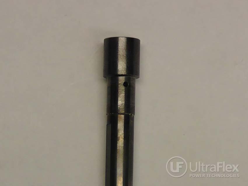
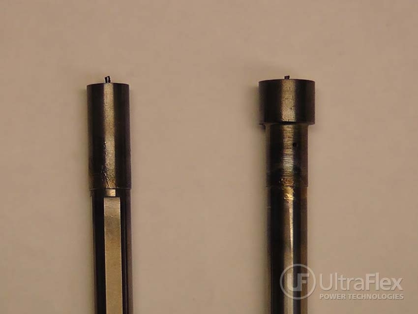
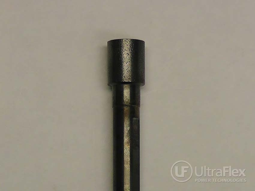
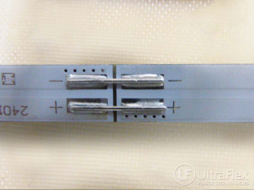
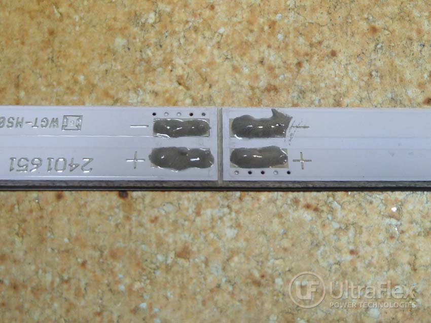
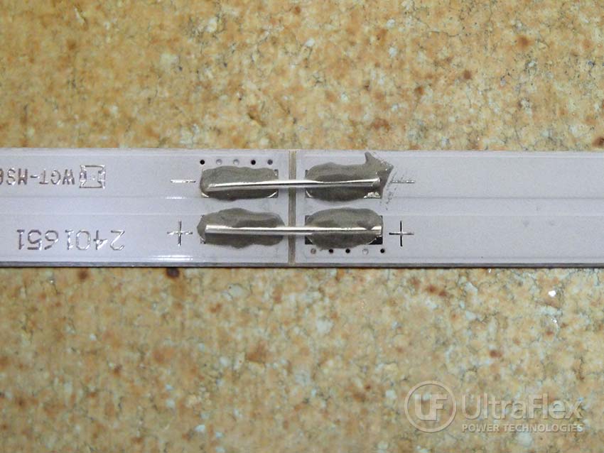
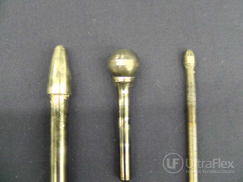
The completed brazed parts.
Video
Video 1

Video 2


Ultraflex Power Technologies provides Induction Heating Solutions for your heating challenges. 
Contact us today about your heating application.

Wednesday, July 29, 2015

Application Test: Brazing Aluminum to Aluminum

The objective of the application test is brazing Aluminum to Aluminum in less than 15 seconds. We have aluminum tubing and an aluminum “receiver”. The brazing alloy is an alloy ring, and has a flow temperature of 1030F.
Brazing Aluminum to Aluminum
Completed assembly by Brazing Aluminum to Aluminum
Materials
• Aluminum tube: 0.167” OD, 0108” ID
• Aluminum component: ID .1675”, depth .288”, chamfer at top area is 0.2375” ID max
• Braze alloy in the form of two-turn alloy ring
• Flux
Key Parameters
Temperature: 1030F
Power: 2 kW
Time: 14 seconds
Frequency
107 kHz
Process:
  1. The Aluminum component and tube were assembled together with the alloy ring. Flux was added.
  2. The part was positioned in the induction coil.
  3. Several tests were conducted with different cycle times to confirm the heating time for a good braze.
  4. At 15 seconds the assembly melted.
  5. At 14 seconds, we had success for brazing aluminum to aluminum, and a good quality braze joint was achieved.
Results/Benefits:
The 5 kW system requested by the customer, will meet the customer’s time requirements for brazing.
  • Precise control of the time and temperature
  • Power on demand with rapid heat cycles
  • Repeatable process, not operator dependent
  • Safe heating with no open flames
  • Energy efficient heating

Pictures
The aluminum tubing and aluminum component to be brazed, shown separately and as assembled.

The Aluminum component and Aluminum tubing were assembled together with the alloy ring.  
Flux was added. The part was positioned in the induction coil. 
Induction power was turned on, and the part began to heat.
Picture shows approximately 2 seconds after power has been applied.
The part continued to heat.
Picture shows approximately 4 seconds after power has been applied.
The part continued to heat.
Picture shows approximately 10 seconds after power has been applied.
The part continued to heat.
Picture shows approximately 12 seconds after power has been applied.
Power was turned off after 14 seconds,
and the process of brazing aluminum to aluminum was complete.

The completed Aluminum to Aluminum braze.
Video

Ultraflex Power Technologies provides Induction Heating Solutions for your heating challenges. 

Contact us today about your heating application!

Tuesday, July 21, 2015

Brazing Carbide Tips to Steel Impeller


Braze carbide to steel
Equipment

Materials
Steel Impeller
Carbide – 0.085” thick x 0.877” wide
EZ Flo 3 braze paste

Key Parameters 
Test 1 (Used Carbide Tip Removal)
Temperature: Approximately 1450F
Power: 4 kW
Time: 8 seconds
Frequency: 111 kHz

Key Parameters 
Test 2 (Replace Braze Carbide Tip)
Temperature: Approximately 1450F
Power: 29/3 kW
Time: 14 seconds
Frequency: 109 kHz
Carbide Tipping is specific brazing process by which a hardened tip material is applied to a base material to produce an extremely hard cutting edge.  When using induction heating, the tipping material is brazed to the base material with temperatures up to 1900 degrees F.
Process for Debrazing:
  1. White flux was added to the used carbide tips at the interface area prior to heating.
  2. The Parts were brought up to temperature, and the part was tapped lightly to help loosen and remove.
Process for Rebrazing:
  1. The surface area was cleaned and lightly ground to provide a flat smooth interface area for the replacement braze cycle
  2. Alloy was added and the carbide positioned on the impeller.  The coil was positioned and angled around the part.
  3. The power was reduced to permit a soak time and ensure proper alloy wetting.
Results/Benefits:
  • In-house operation of replacing carbide tips enables fast turnaround time, and minimizes downtime.
  • Precise control of the time and temperature
  • Power on demand with rapid heat cycles
  • Repeatable process, not operator dependent
  • Safe heating with no open flames
  • Energy efficient heating
  • Precise heating
Pictures

The carbide tip is positioned to remove the used carbide.  Heat time is 8 seconds.

The impeller following the carbide tip removal.

Videos
Carbide Tip Debraze

Carbide Tip Rebraze

Carbide Tip Rebraze (closer view)

Ultraflex Power Technologies provides Induction Heating Solutions for your heating challenges. 
Contact us today about your heating application.

Monday, July 20, 2015

Application Test: Induction Braze Carbide Cap to Steel Shaft

Objective of Application Test: Induction Braze a Carbide Cap to a Steel Shaft - including several shaft and cap sizes. The customer currently uses a torch process, but would like to change to induction to reduce scrap and rework and improve quality of braze. 
Brazing the carbide cap to the steel shaft

Equipment
Materials
• Carbon steel
• magnetic carbide caps
• Alloy – EZ Flo 3 paste
• Test 1: Shaft Diameter: 0.5”
• Test 2: Shaft Diameter: 0.375”
• Test 3: Shaft Diameter: 0.312”
Key Parameters
Test 1 (Shaft Diameter: 0.5”)
Temperature: approximately 1450F
Power: Pre-curie – 3.3 kW
Time: 11 seconds
Frequency: 77 kHz
Key Parameters
Test 2 (Shaft Diameter: 0.375”)
Temperature: approximately 1450F
Power: Pre-curie – 1.8 kW
Time: 8 seconds
Frequency: 76 kHzKey Parameters
Test 3 (Shaft Diameter: 0.312”)
Temperature: approximately 1450F
Power: Pre-curie – 1.7 kW
Time: 7.5 seconds
Frequency: 76 kHz


Process:
  1. Paste alloy was applied to the cone shape top of each steel shaft.
  2. The cap was set on top and rotated to distribute the paste alloy.
  3. Each assembly was positioned in the coil and heated.
  4. Preliminary heat tests were conducted using tempilaq paint to estimate the heat cycle to 1450 degrees F.
Results/Benefits:
  • Precise control of the time and temperature resulting in improved quality and consistent result
  • Power on demand with rapid heat cycles
  • Repeatable process, not operator dependent
  • Safe heating with no open flames
  • Energy efficient heating
Pictures

Video


Ultraflex Power Technologies provides Induction Heating Solutions for your heating challenges. Contact us today about your heating application.

Induction Soldering of PCBs to reduce Cycle Time

The customer previously used a manual solder process, with the time to join 7 PCB’s 1 minute 45 seconds. This is just the solder time, and does not include the time to apply the solder paste and place the jumper across the PCBs in the paste. Our goal is to use induction soldering to reduce the cycle time while producing a high quality solder joint.
Jumpers are used to solder two adjacent PCB's together.
Using Induction, the time to solder 7 boards has been reduced from 105 seconds to 12 seconds.

Equipment
Materials
• Soldering wire
• Soldering paste
Application of the solder paste with a stencil is recommended. This will provide improved process control, better repeatability, and avoid any residues.
Key Parameters
Temperature: 300° C
Power: 3 kW
Time: 2 sec to join two boards; 12 seconds to join 7 boards (this is an 89% reduction in the time it previously took to solder the 7 boards).
Frequency200 kHz
Process:
  1. Apply the solder paste on the pads of the printed circuit boards.
  2. Place the copper jumpers in the solder paste across the pads of the adjacent PCBs.
  3. Position the induction coil over the copper jumpers and pads.
  4. Apply power to the UPT-S5, and heat for 2 sec. That’s the time to heat one joint, and join 2 boards.
  5. Confirm electrical continuity of across the jumpers by testing LED’s on the printed circuit boards.

Results/Benefits:
Induction heating provides:
  • Strong durable joints
  • Selective and precise heat zone, resulting in less part distortion and joint stress
  • Less oxidation
  • Faster heating cycles
  • More consistent results and suitability for large volume production, without the need for batch processing
  • Clean and safe heat application, without pollutants

Video of the Soldering Process

Pictures of the Soldering Process
Solder paste is applied to the pads of the PCBs to be joined.
The jumper is positioned across the PCBs in the solder paste.
The boards are positioned under the Induction Coil for soldering.
The finished solder joint.


Tuesday, July 14, 2015

Pre and post weld heating with induction

In today’s mining and oil exploration, expensive stainless steel pipes are being replaced by regular steel alloy drill-pipes. From the recently discovered sea fields to the pre-salt layer zone 7km below sea level in Brazil, these changes are taking place. The regular steel drill-pipes are welded every 12 meters and are coated with a special epoxy. 

Regular welding is not as effective for walls thicker than several centimeters. These pipes must be preheated for the welding process to be effective. The most commonly used preheating methods are: electrical resistive, gas flame, and induction heating. Oil and gas pipeline manufacturers and installers are turning to the fast, accurate, and uniform heating of induction heating systems.


Induction welding line
Welding line (12 meter long pipes)

For butt welding, induction heating is commonly used to preheat the joint area to 150-300°C (depending on the WT). This preheating prepares a consistent, quality weld, significantly improving fluidity and quality. After welding, the joint area can be heated to 600-650°C for thermal stress relief of the welded area.

Traditional gas flame or resistive heating systems can also be used, but are often impractical when higher temperatures are required. Not only are they too slow to meet the cycle times demanded by the industry, but also the heating can be inaccurate.

Only induction heating can guarantee uniformity around the full circumference and bandwidth of the weld joint. Among the three energy sources mentioned above, induction heating requires the least amount of time for preheating, has the highest energy efficiency, and is the safest and most cost effective. Perhaps most importantly, while the costs of induction equipment are higher at the beginning, the efficiencies offered will offset the added cost. The better and safer environment for workers will help optimize both productivity and quality.


Induction Gauge Coils
Gauge Coils

Automatic Welder
Automatic Welder

Hanged Induction Station on rails
Work head on rails


Other benefits of induction heating include:

  • Variable control over temperature/time parameters. Minimal damage of factory coating and no deleterious surface residues. 
  • No open flames or exposed heating elements.
  • Reduces energy costs and eliminates the needs for large gas storage area.


by Reynaldo Alves

Reynaldo brings to Ultraflex 30+ years Electronics background with Technical Sales and Organizational Management including over 10 years’ experience with induction heating including wire heating, nanoparticle research, heat treating, melting, and other precision applications.


Friday, July 3, 2015

Levitation melting 2g of aluminum


Objective
Levitate and melt 2g of Aluminum using a specially-designed induction levitation coil. Traditional melting applications impart impurities into the melted material. This can be used for a well-controlled high-purity melt for precise materials research.
Equipment

Materials
2g Aluminum metal
Test tube

Key Parameters
Power: 1.72 kW
Frequency: 98 kHz
Process:
  • The 2g aluminum sample was placed into a test tube
  • Current was run through the levitation coil
  • The sample was loaded by passing the test tube through the coil and allowing the aluminum to float out by levitation.
  • With time, the levitated aluminum melted and stabilized.
Results/Benefits:
  • Precise, non-contact containment of the sample
  • No crucible: High-purity of the sample
  • When the process is finished, the sample can be removed by turning off the power supply and allowing it to exit from the bottom of the coil.

To learn more, visit: ultraflexpower.com/application/